Using CAIRIS as tool-support for STPA
Overview
STPA (System-Theoretic Process Analysis) is a hazard analysis technique; it assumes accidents may be caused by unsafe interactions between system components, which may or may not have failed. CAIRIS can support the use of STPA because the concepts it supports are analogous with those required by STPA.
You may wish to use pen and paper to start your design exploration with STPA; this is entirely appropriate. However, as the STPA outputs become more complex, software tool support becomes useful. CAIRIS can help by providing automatic traceability between STPA elements, automatic generation of visual models and documentation, and reasoning support to help identify and validate casual scenarios. As such, using CAIRIS can to support your use of STPA could improve your efficiency as your analysis evolves.
One particular benefit of CAIRIS is its interoperability. For example, you may wish to rely on Excel to maintain a hazard list or other control structure data. Because Excel is machine readable by many scripting tools, it is comparatively easy to turn Excel spreadsheets into CAIRIS models, which can be incrementally imported into CAIRIS, or convert CAIRIS models back to Excel.
In the following sections, we describe how CAIRIS can help with the four steps of STPA. Like the rest of the CAIRIS documentation, please help us help you by raising an issue about anything unclear, inaccurate, or to raise request additional content you think might be useful.
Step 1: Define purpose of the analysis
Identifying losses
You can add losses by creating obstacles with a Loss category.
Identifying system-level hazards
You can add hazards by creating an obstacle with a Hazard category. To link hazards to losses, add a KAOS associatio where the head element is the loss obstacle, the tail element in the hazard obstacle, and an And association type to indicate that the refined hazard needs to be satisfied for the loss to be achieved.
Defining system-level constraints
System-level constraints can be modelled as goals in CAIRIS. To indicate that the constraint attends to a hazard, add a KAOS association where the head element is a hazard obstacle, the tail element is the goal representing the constraint, and the association type is Resolve, to indicate the constraint is necessary for preventing the hazard.
Refining the system-level hazards
Additional obstacles and KAOS associations can model how hazards can be refined.
Step 2: Model the control structure
This entails creating a data flow diagram (DFD), where processes and data stores are analogous with STPA control algorithms and process models respectively. To create processes and data stores, you need to create use cases and information assets respectively. These DFD elements should be encompassed in a trust boundary; the type of trust boundary can be set to be a Controller, Controlled Process, Sensor or Actuator.
DFD elements interact with each other via data flows. When creating data flows, the type of these data flows can be set as Control, Feedback, of Information. You also need to specify information asset/s carried by each control, feedback, or information flow.
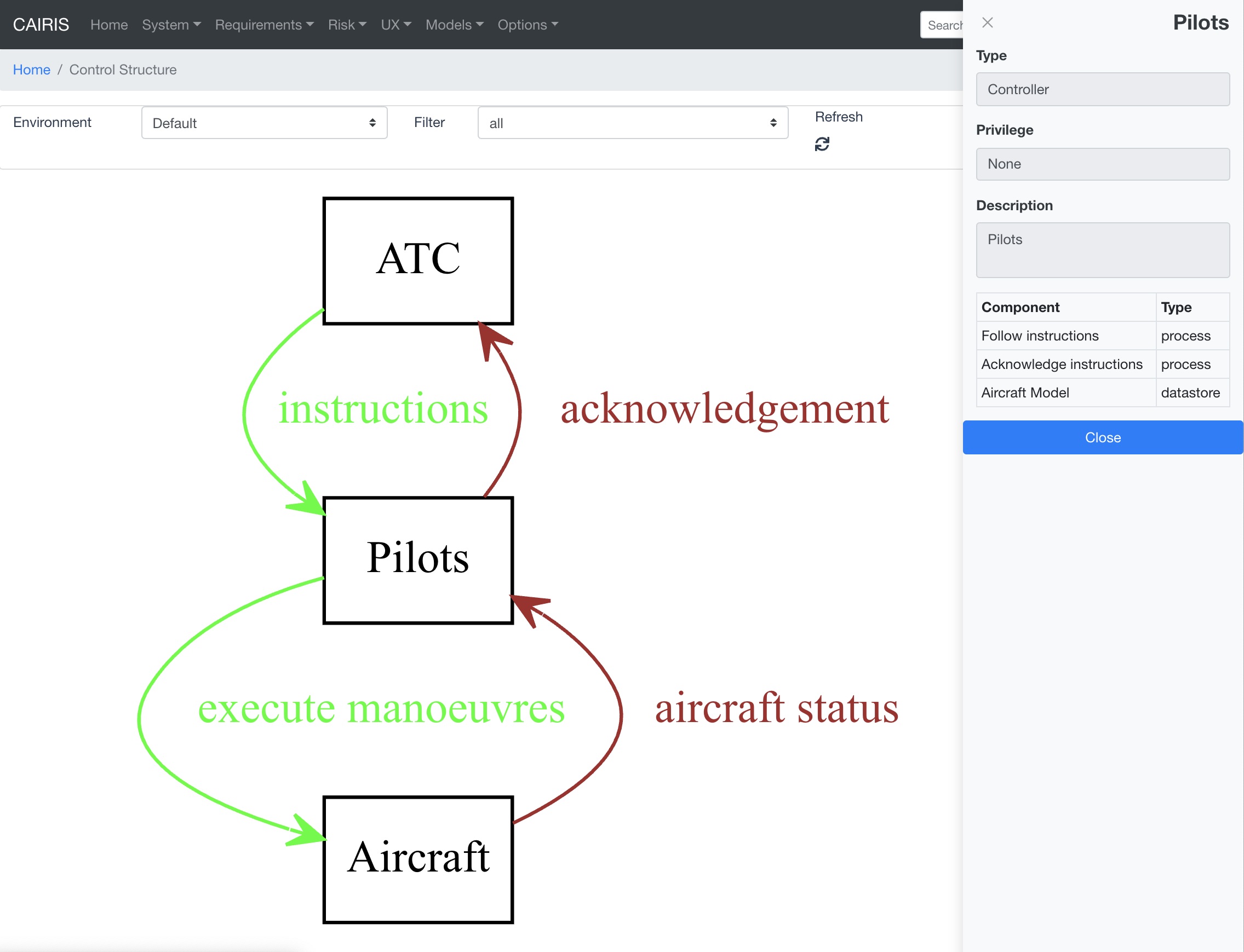
CAIRIS now supports a control structure model. As shown in the figure below, which is based on ATC example in this STPA tutorial . CAIRIS automatically visualises the relationship between trust boundaries - in their role of controllers, controlled processes, sensor or actuators - and entities, which could represent external systems.
Step 3: Identify unsafe control actions
Unsafe control actions can be represented as obstacles. Once identified for a control flow, these can be associated with data flow. When associating the obstacle, you need to indicate the appropriate UCA keyword (does not provide, provides, provides too early, provides too late, provides out of order, stopped too soon, applied too long, not applicable) and provide some textual context for the unsafe action. In the future, we may add support for automatically generating these obstacles based on the data flow elements, keyword and context but, for now, this obstacle needs to be manually created.
Once the obstacle has been created, this can be linked with hazards using KAOS associations, where the head elements are hazard obstacle, and the tail elements are obstacle constituting the unsafe control actions.
Step 4: Identify loss scenarios
Tasks can be created and linked to hazards and system constraints using the KAOS associations, i.e. where the task is the tail element and obstacles and/or goals are head elements. Tasks might be used to illustrate why unsafe control actions occur, and why control actions could be improperly (or not) executed – possibly in the presence of safety constraints – leading to hazards.
CAIRIS model validation checks can highlight design-level issues that could lead to such scenarios. We are currently working on STPA specific validation checks, e.g. to identify control actions without feedback.
Supporting other STPA outputs
KAOS associations can be created to indicate system roles that are responsible for the satisfaction of goals (i.e. safety constraints).
CAIRIS can automatically generate requirement specifications from CAIRIS models. We are considering the idea of generating a more specific STPA specification document. We welcome requests for what its format should be.